Thursday, March 28, 2013

Lotus Malaysia 2013 Upgrades


In Malaysia Lotus brought forth a couple of upgrades that included a new front wing endplate, a new tunnel under the exhaust and a new diffuser gurney flap.

After introducing their brand new front wing in the last preseason test in Barcelona which featured new upper elements, new cascade winglets and new endplates, Lotus have introduced a slight modification to the front wing endplates in Malaysia. The upper part of the endplate is now split into two elements. The change can be seen in the illustration below. This is done to improve flow around the front wheels, as the split endplate will now induce a stronger vortex and aid the flow of air around the front wheels and incidentally reducing their wake and improving flow towards the rear of the car.


New Front Wing Endplate

Old Front Wing Endplate
The team also introduced a new tunnel under the Red Bull inspired exhaust ramp, which much like the upgrade Red Bull introduced in late 2012, the tunnel is now smaller. The tunnel is there to improve flow at the rear of the car as the so called coke bottle is now lost. By reducing the size of the tunnel, they are achieving cleaner flow towards the rear of the car as well as reducing the drag induced by the larger tunnel.


New Sidepod Tunnels

Old Sidepod Tunnels

The third upgrade introduced by Lotus is a new diffuser gurney flap, which is actually no longer a gurney flap. Red Bull started a trend in 2011 of replacing the gurney flap with a small airfoil on top of the diffuser’s trailing edge. Since then most teams have followed. Lotus had already replaced the gurney flap in the central section of the diffuser with the airfoil, and have replaced the gurney flap on the edges of the diffuser last weekend in Malaysia as can be seen in the illustrations below.


New airfoils on top of the edges diffuser
Old gureny flaps on the edges if the diffuser

The last upgrade lotus introduced is a slightly revised barge board which had already been previously upgraded featuring slots to strengthen the vortex induced and keep the airflow attached behind the barge boards.


Thursday, March 14, 2013

Red Bull Winter Testing Upgrades Report


Red Bull ran their version of the DRD (Drag Reduction Device) during the second day of the second and last Barcelona test. 

Last year, from Singapore onwards Red Bull raced with their own version of the Double DRS (Red Bull 2012 DDRS). As such devices have been outlawed for this year. Teams have tested passive drag reduction devices, similar to the one Lotus introduced in the summer of 2012.  Red Bull’s DRD however is neater than Lotus’.


Near top speed, air will bleed through the vertical duct, breaking up the flow, reducing downforce and subsequently drag. The system is made up of three main parts. The first is the intake which is not apparent, but it is hidden inside the roll hoop. The second is the outlet through which air will flow through at all times which is either below the beam wing are behind the rear crash structure above the diffuser and the vertical duct which blows on the rear wing.


During the third day, the team introduced their major upgrade package which included a new front wing, new nose,  and a slightly revised tunnel underneath the coanda ramp.
New Front Wing

Old Front Wing
Red Bull has changed their cascade wing philosophy, as it now curls down to meet the footplate vertically together with the endplate, similar to the way the main profile of the front wing is shaped. Additionally, there are now slots in the endplate to keep the airflow attached. This will improve the way the air flows around the front wheels.


The new nose is now slightly lower, and there is a new vanity panel which is no longer chamfered. The new nose still sports the holes at the bottom and at the top which form the S-Duct (S-Duct Explanation).

New Nose

Old Nose


Ferrari Winter Testing Upgrades Report


Ferrari was one of the first teams to introduce their major upgrade. On the second day of the second test in Barcelona, once the rain had stopped we saw part of the upgrade package, as some more parts were tested in the last day of the test and the rest of the parts will be tested tomorrow Friday 15/03/2013 during free practise of the Australian GP.
  
While the concept did not change, the new sidepods now bend down more. As a result the coanda ramp is now lower to better aim the exhaust plume towards the diffuser’s edge.  


New Sidepods

Old Sidepods
As well as a changed coanda ramp, the cooling outlets have changed.  In the following drawings I have moved the suspension and rear wing so that you can see what has changed more easily.

New Cooling Outlets

Old Cooling Outlets
The new version sports wider cooling outlets just behind the exhaust and coanda ramp while in the older version they were slimmer. However, in the original version which is very similar to the one present on the F2012, there was a second cooling outlet further back which also featured two cut-outs on each side. The second cooling outlet has now been removed, thus the need for the wider outlets behind the exhaust.

New

Old
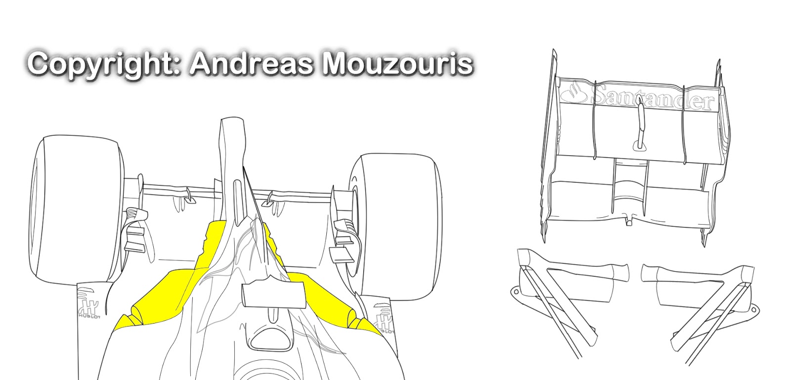
 The new front wing was briefly seen on the second day of testing and brought back for the last day.

This new front wing adds yet another element on its outer tips, together with new cascade wings, endplates and the adjustable upper element.

New Front Wing

Old Front Wing
 The new element on the outer tips, allows the wing to curve outwards at a larger angle to create more downforce and direct a larger portion of the airflow around the wheels.
The new endplate is covering up a portion of the open area that allowed airflow flowing over the top of the wing to flow to the outside. This will create more downforce. As well as the new endplate, the footplate now features a slot which is an innovation by Ferrari it is the first time seen on a car, ever.

New Front Wing Endpate

Old Front Wing Endpate

 The new cascade element is no longer divided into two different parts, instead it is one winglet only much wider than before. The fence that divided the two cascade elements on the older version has now become a vertical fence which will induce a stronger vortex in the attempt two direct the airflow around the front wheels as efficiently as possible.
At the top of the endplate a smaller winglet has been added, similar to the one used by Red Bull. 

The inner adjustable element of the wing has been revised, with its inner extremities now taller than before.

Moving slightly upwards, we will find the new strake running along the sides of the nose that was first introduced in the last day of the first Barcelona test but was slightly revised in the second one. The strakes are there for legality purposes, so they were tested before Melbourne.


On the last day of testing, the team tested more new parts. On of which was the new rear wing. The wing now features smaller v-cutouts on the top of the upper element. In addition, the endplate has been revised and the gills are now slightly smaller than before. Those gills bleed the high pressure air from the inside of the wing to the outside, reducing drag by weakening the strength of the vortex shed at the wing tips.


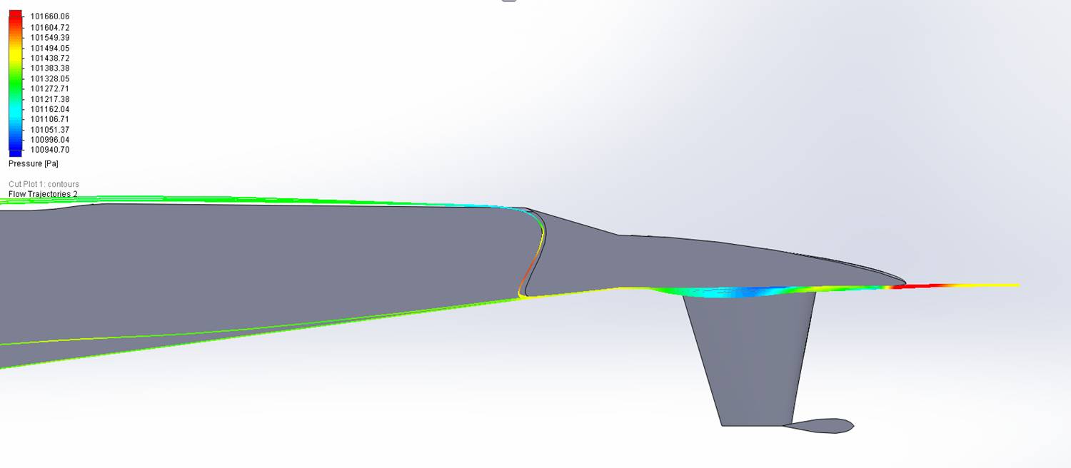
The last new part tested was a new diffuser which still features the airfoil shaped gurney flap on top of the diffuser’s trailing edge, but it now curves downwards instead of stopping at the edges. Also, the diffuser no longer dips down where the two main vertical strakes are located. 


Monday, February 25, 2013

The new era is ever closer - 2014 Turbocharged Engines

Renault Sport F1:

WHAT WILL CHANGE

The gauntlet the FIA has thrown down to F1’s engine makers for 2014 is to reduce the quantity of fuel needed for a Grand Prix by almost 40 percent, yet still maintain the same level of performance and power outputs (i.e. around 750 horsepower) as today. This change to the ground rules is poised to spark a major technological metamorphosis and a whole new challenge for the sport’s engine experts.

The discussions that took place to prepare the new regulations led to the choice of a new engine technical definition.

The countdown to 2014 is already well under way as the engineers turn their attention to the development of what is termed a ’power unit’ that combines a downsized turbocharged engine with two electric motors to recover braking and exhaust heat energy.

Downsized internal combustion engine 
Switch from a V8 to a V6 architecture 
Cubic capacity reduced by one-third from 2.4 to 1.6 litres 
Turbocharging (single-stage compressor), plus engine torque capped at 15,000rpm for a power output of approximately 550 horsepower

New ‘Energy Recovery System’ (ERS): kinetic energy (ERS-K) and exhaust heat energy (ERS-H) is recovered by two electric motor-generator units named MGU-H and MGU-K.


THE NEW RESTRICTIONS SPECIFIED BY THE 2014 FIA REGULATIONS

A double-restriction concerning fuel 
The amount of fuel that can be used during races has been reduced : the maximum quantity of fuel that may be carried by the car during a race will be reduced to 140 litres. Energy management will become a major factor of race strategies. 
Fuel flow reduced : the maximum fuel flow rate will be reduced to 140 litres/hour, making optimisation of every gram of fuel vital for cars to go as fast as possible on a given quantity of fuel.

A double restriction concerning the flow of electrical energy 
The amount of energy that can be recovered during each lap has been reduced 
The amount of energy that can be restored has also been reduced

Development costs have been limited and the number of engines each driver can use in the course of the season has been further capped: five per driver in 2014, then four per driver from 2015 (compared to eight per driver at the moment). The technologies and materials employed must be similar to those used for production engines.

Energy efficiency, the new aim in F1

This step from a competition that has traditionally placed the emphasis on power with little consideration for fuel consumption to a new era focused on energy efficiency and reduced fuel consumption (for the same level of performance) is a real revolution for the world of F1.

As a pioneer of engine downsizing as long ago as the 1980s, Renault benefits from an extensive understanding of the turbocharged V6 architecture. Meanwhile, thanks to the electric vehicle programme it instigated in 2009, Renault also enjoys an edge in the field of electric motor technology. These are two indisputable trump cards as it prepares for the switch from normally-aspirated V8s to electrified V6 turbocharged power units.


Sunday, February 17, 2013

Red Bull and Sauber S-Duct

In the past two years Red Bull have been utilising holes around the nose of the monocoque. In 2011, said hole was placed at the bottom of the nose to cool the electronics and reduce the boundary layer development. Something which they also did last year while also adding the so called letter-box hole at the top of the nose. Its purpose, largely, was to overcome the issues of the stepped nose and cool the driver. This year however they have copied an innovation seen on last year’s Sauber. The, so called, S-Duct. 


This year both Sauber and Red Bull have adopted this solution. Both teams decided to not to completely cover the stepped noses with a modesty panel and instead use a smaller modesty fairing. A decision which, according to Adrian Newey, saves weight. Keeping the stepped nose though, means that the problem of keeping the airflow on top of the monocoque attached remains. In addition there is high pressure generated at the bottom of the nose because of its height. Red Bull has kept the hole under the nose and by ducting airflow using an s-shaped duct, it exits facing rearwards on top of the nose.

The lower slot relieves some of the high pressure and the boundary layer build-up at the bottom of the nose, bleeding some of the high pressure on top of the nose which in turn keeps the airflow attached behind the step of the nose and prevents the build up of a thick boundary layer on top of the monocoque.  

Below the flow trajectories on the top and the bottom of th enose without the s-duct are illustrated. Note the 3rd and last picture where you can see the formation of the thick boundary layer.